When you’re part of a small crew, you want to be able to estimate what lights you can use in a location.
Unfortunately, there isn’t a simple tool, app or formula that can give you a definitive answer. And, nobody wants to learn arcane formulas and electrical engineering concepts.
There are two possible solutions to this problem:
- Get assistance from a Gaffer or Best Boy, or
- Do it yourself
If you have the budget, there is no excuse for not involving a Gaffer or Best Boy (Electric) in your estimation of lighting equipment. Gaffers know more about professional film light fixtures and power than the average person.
When I say involve, you don’t have to hire the Gaffer or Best Boy everyday if you can’t afford it. But you could pay them for a day or two to help you understand what might and might not work.
Trust me. A timely consultation will save you time, money, and maybe someone’s life.
Important Warning and Disclaimer:
Please hire a Gaffer or Best Boy (Electric), even if it is for a day or two, to help you figure all this out.
This article is for information purposes only. No action is to be taken based on any of the formulas, ideas, information or suggestions provided here. In all cases you must take the help of a certified and experienced professional Gaffer, Best Boy Electric or Lighting Technician (Electrician).
You are totally responsible for your actions. Before you play with electrical equipment and power supplies, please ensure you know local laws and regulations concerning the use of electrical and electronic devices, emergency first aid procedures for burns and electric shocks, where the nearest hospital is and how to get assistance.
Always wear protective clothing and shoes.
This ‘guide’ does not substitute for professional help. I have left out a lot of things, and have oversimplified concepts just to help your understanding. Little knowledge is dangerous.
Just understand, don’t apply it.
Who is this guide for?
My aim is to keep things as simple as possible. I’ve taken the liberty to eliminate anything that is not relevant to this purpose.
I’ll use analogies instead of formulas. Except this one time.
I’m only going to give you one formula – one formula to rule them all:
Power Formula
Power (W) = Voltage (V) x Amperes (A) x Power Factor (PF)
That’s it. No more formulas.
This article will help you:
- Understand how an alternating current (AC from here on) power supply works.
- Understand why you might not get the full power you are ‘promised’ on the label.
- Estimate how much power a portable generator or mains power supply can really deliver.
- Estimate how many lights you can use on it.
- Learn to communicate effectively with your Gaffer or Best Boy Electric
Let’s get started.

What is Voltage? What is Current?
Imagine you want to set a trap for cute little guinea pigs. You dig a ditch so he’ll fall into it. The bigger the ditch, the better the chances of him falling.
This ditch is voltage.
It has the potential to trap your enemy. The bigger the ditch, the greater the potential,.
When your enemy falls into it, he generates current. Current flows.
The ditch (voltage) allows the possibility of current (fall). If you want to generate a current, your best bet is to ensure there is a voltage ready somewhere.
A wall socket is one such ‘voltage-ready’ point in space, waiting for some device to be plugged in so current can flow. Electrical devices need current to work.
Pull out the device (or switch off the socket) and the current stops flowing. The device stops working. The wall socket waits for the next device.
The voltage at any point is measured in Volts (V).
Current is measured in Amperes (A).
The most important thing to know about V and A is that they are different for DC (batteries and DC generators) and AC (AC generators and mains electricity).
Both are measured in Volts and Amperes, but the way they are measured is different. Sometimes, finding a one-to-one correspondence is impossible. Bottom line, don’t use DC formulas for AC, and vice versa.
In this guide, we will only refer to AC power. The formulas only apply to AC.
What is Power?
If your ditch is large enough, you can trap many guinea pigs.
If your ditch is too small, you have less power over the guinea pigs. This is one way of using the word ‘power’.
In the world of mechanical engineering, a horse has power – it has power to pull a cart. Steam engines and fighter jets have the power to carry payloads.
Electricity has a similar kind of power. It can move things too – table fans, motorized sliders, trains, computers and even information in your brain.
This is why we use the word power in electricity. We use electricity to move things, too.
This power, the ability to move things, is measured in Watts (W).
Power, voltage and current are related like family:
Power Formula
Power (W) = Voltage (V) x Amperes (A) x Power Factor (PF)
We have papa bear, mummy bear and baby bear in this cute family. But what is this “PF”, the Goldilocks?
The Power Factor (PF)
The power factor (PF) will always be between -1 and +1. For our purposes, its value will always be between 0 and 1.
What happens when you multiply a number with a number that lies between 0 and 1? The value of the number reduces. The only way to get the full value back is if the power factor is 1. Anything lower is a losing proposition.
Why is there a power factor? Trust me, you don’t want to know.
But this next bit, you will want to know.
Real power and Apparent power
Theoretically, you want all the power possible.
Let’s slightly alter our formula:
W = V x A x PF = [V x A] x PF
V x A is called the Apparent Power.
W is the Real Power.
- Real power is the power a device thinks it draws.
- Apparent power is the power it really draws.
Real power can never be greater than the apparent power, only lesser or equal.
What’s the point of knowing this? It is important because some devices display the real power while others display the apparent power:
- When you see a device with a power rating in Watts (W) or KiloWatts (KW, meaning 1,000 Watts), the rating reflects the real power.
- When you see a device with a power rating in VA or KVA, the rating reflects the apparent power.
Beware, though! Some manufacturers and professionals interchange the two. Why? Due to ignorance, laziness, false marketing or whatever. Some countries have strict regulations on how electrical devices need to be rated and displayed. Other countries might not.
Since we’re talking about light fixtures, ask yourself:
Why do we say an HMI light is 1.8K or 4K? K-what? Is it KW or KVA?
I hope you’re beginning to see the problem.
Power factors of some lighting fixtures and electronic devices
Here’s a quick list of the approximate power factor (It varies from device to device) for various devices and fixtures:
| Light Fixture or Device | Approximate Power Factor* |
|---|---|
| Tungsten | 1 |
| HMI Electronic Ballast | 0.5 to 0.6 |
| HMI Magnetic Ballast | 0.5 to 0.6 |
| LED | 0.6 to 0.9 |
| Fluorescent Electronic Ballast | 0.6 to 0.9 |
| CFLs | 0.6 to 0.9 |
| Plasma | 0.8-0.98 |
| LCD Monitors | 0.7 |
| OLED Monitors | 0.9 |
| PCs | 0.5 to 0.7 |
| Laptops | 0.7 to 0.9 |
| Battery Chargers | 0.6 |
| If you don’t know, use this: | 0.6 |
What is a good power factor? Anything greater that .85 (85%) is good.
As you can see from the above table, most things we want powered have a poor power factor. A power factor of 0.5 (50%) means that the device draws twice the amperes it is rated for. What a waste!
Many modern power supplies come with something called Power Factor Correction (PFC). It is an additional circuit that is added to bring the PF as close to 1 as possible. Usually the result is above .9 (90%).
To find the power factor of a fixture, look at the electrical specifications on the device. It should be mentioned explicitly. If you have to ask, then there’s something wrong.
Rule of thumb: If any of the values are not explicitly available from a manufacturer’s written technical specifications, then don’t trust that manufacturer.
For every device you need powered, find its power factor and write it down somewhere.
That’s the first step.
Now on to something totally different.
What is Single-phase and Three-phase power?
Let’s start with an analogy.
Imagine a battery:

Now imagine two batteries connected to each other in this way:

If each battery is 1.5V, then together, they provide 3V.
Now, imagine this quirky scenario:

Don’t worry about the polarity of the batteries, it’s just an analogy. If you measure between any two points you get 3V:

Why would anyone want to create power in this strange ‘Y’ design? That’s not for us to know at this time.
All you need to understand about three-phase electricity is: If current travels through one wire in single-phase, it travels through three in three-phase. Three-phase power is AC.
Where the three batteries meet is called Neutral (N).
If you measure from the tip of each battery to its rear (N), you’ll get 1.5V.

This is single-phase.
I might have given the wrong impression that the voltage of three-phase is always twice the value of single-phase, but that’s not the case. In fact, the voltage of three-phase is 1.732 (?3) times that of single-phase.
What we usually get on household wall sockets is single-phase, both at homes (Residential) or in offices (Commercial).
Three-phase is usually left for transmission and for factories, industries (Industrial), etc. There are exceptions, of course. If you have a three-phase supply in your bedroom, don’t freak out!
How does Electricity get Everywhere?
Electrical distribution is one of the great triumphs of the human race. Without it we would be still having candle-lit dinners.
Here’s how electrical distribution works:
First, something physical must move or react. When it does, it generates electricity.
The thing that moves is a turbine (think: ultra large ceiling fan). How would you move a ceiling fan without electricity? You could turn the blades with your hands. Or, you could:
- Spray the fan with water – Hydroelectric power, usually carried out by dams using the power of moving water from a great height.
- Blow air – Wind turbines.
- Put rockets on it – Burning coal or other fossil fuels.
- Put a small atomic bomb between the blades and set it off – Nuclear power.
Together, these are called power stations or power plants. The power plant generates three-phase electricity at a certain voltage.
Power begins at the power plant:

Quickly, before power is lost, it is transmitted via power lines over large distances:

The power transmission lines end at substations. The most important thing about sub-stations is that they are able to divide power into different ‘groups’ for different people:
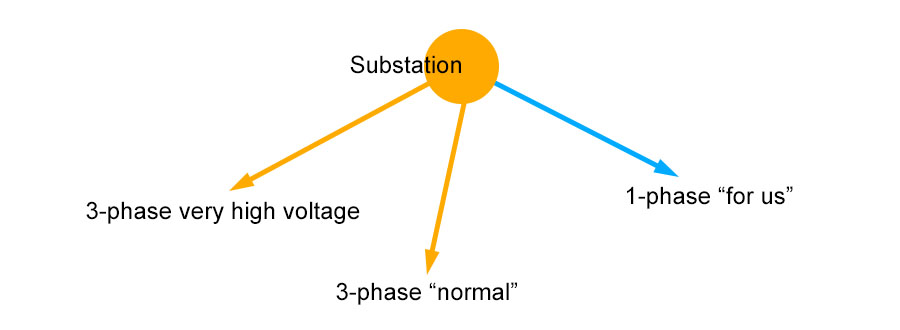
The power you receive in your home is single-phase power. Some households or large apartment complexes might get three-phase power, but it is usually split into single-phase lines for each building.
The substation might also cater to really large industries, small industries, further transmission, etc. Electrical power of every kind imaginable can be created from the substation.
The doohickey that does this is called a Transformer (not the robots). Its job is to convert voltage from one level to another.
The further you get from the substation, the lower the voltage gets. This is because, due to various reasons, energy is always lost during travel. Every transmission line or cable (even the one going from your mouse to the computer – wired or wireless) will create a loss.
At every end point in the electrical distribution chain, you’ll find a transformer that is waiting to raise the voltage to acceptable levels. Non unlike an energy drink at the end of a long run!
As you can see, the entire chain of events is handled by two kinds of tools:
- Generators – they convert ‘something physical’ into electricity.
- Transformers – they raise or lower the voltage.
Single-phase into your home or office
From the transformer a cable travels (either overhead or underground) into your home, and ends up in a box called the electrical Distribution Board (DB) (also called ‘panel’):

The mains supply (in blue) is connected to a Circuit Breaker (CB), in pink.
There are many kinds of circuit breakers. The role of a circuit breaker is to trip (or stop, or break) the circuit if something goes wrong. This happens when current flows through something that it is not supposed to. Circuit breakers save lives and equipment. And, their use is mandated by law in most countries.
After the main breaker, each part of the cable is split into:
- Line or Phase – the wire that carries current to the board.
- Neutral – this is zero volts. It exists to close the circuit (the bottom of the ditch you dug for the guinea pigs. If there is no bottom, they’ll fall forever).
- Earth or Ground – this is also ideally at zero volts. It exists to provide a quick path for any unwanted current. To where? To the ground or earth!
If the mains supply has an earth wire, it will be earthed or grounded at the transformer to the substation all the way back to the power plant. What if there is no earth wire? We’ll need to create it, but that’s outside the scope of this article.
If you don’t see an earth or ground wire, or have no idea how to proceed from this point, hire an electrician. Period.
In the above image, the three wires terminate at rectangular metal plates called busbars. Busbars help reduce wiring inside the DB, and keep things neat and tidy. Their other job is to ensure every circuit gets an even voltage.
From the busbars, you can start building circuits. A circuit is a closed loop. Notice the direction of the arrows in the above image – the line/phase will take current from the mains and supply it to the circuit.
Neutral should ideally remain at zero. If a device uses up all of the current, then nothing should flow through neutral. In case it does flow, neutral is connected to Earth. This way, both Neutral and Earth are ensured zero volts under normal conditions.
Remember, if the voltage is zero, current cannot flow.
What happens in a Short Circuit?
The reason we use the word “Earth'” or “Ground” is because that’s where the extra electricity is supposed to go.
Let’s say for some bad reason current touches the outer frame of a fresnel light, and a poor soul happens to touch it.
There are three ways for this extra current to flow:

- If the fixture is grounded, it will flow through that.
- If the circuit is grounded, the current will flow back to the DB and out. If not, the ground wire from the fixture must be connected to a rod and driven into the earth.
- If neither are grounded, the poor soul will get an electric shock. This is because we are conductors of electricity, and our contact with the ground allows a path for the current to flow (Ground is always assumed to be zero volts). This is why it is a good idea to wear protective boots and gloves on set.
The parallel lines on the ground (the one that looks like an upturned tree) is the universal electrical symbol for earth or ground.
The universal color of the cable for earth or ground is green+yellow or green. The universal color for neutral is black (but not always). The line or phase wiring can be of different colors. Sometimes, different colors are used to distinguish between different circuits, for easy maintenance. Each country has its own set of color schemes for single-phase and three-phase line cables.
So, what’s the best way to ground something?
You must have a grounded distribution board. You must have excellent circuit breakers that don’t compromise on anything. Every device or lighting fixture capable of giving you an electric shock must be grounded as well.
Usually, this means wiring an earth cable to a metal rod and piling it into the ground. That’s not practical on a film set. This job is best left in the capable hands of an electrician.
Let’s assume you have the sense to consult one.
Let’s move on.
Understanding Wiring and Sockets
Let’s define some terms:
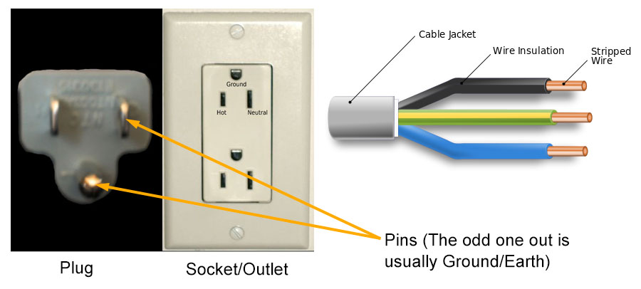
Why do we need plugs? You have something to hold on to without risking electric shock, and you can plug or unplug something easily in one motion.
There are only four ways a cable can be wired:
- Line + Neutral (two wire system)
- Line + Neutral + Earth (three wire system)
- Line 1 + Line 2 + Line 3 + Neutral (three-phase four wire system)
- Line 1 + Line 2 + Line 3 + Neutral + Earth (three-phase five wire system)
The Earth or ground wire need not travel within the same cable, and can be a separate cable. This is preferable.
You might be wondering why, sometimes, you have plugs with just two pins, while on others there are three? Who decides if there should be two or three? Shouldn’t all sockets be earthed (hence have three pins)?
Yes. All sockets should have three pins, but sometimes, you have devices that only offer you a two-pin plug:

Why? Here’s a general rule of thumb: Any device that converts AC into DC immediately to power a low voltage DC device usually has only two pins.
They are allowed to do this for two reasons:
- The Voltage they need to run is low.
- Their devices are insulated, so even if line touches something, nothing on the outside (where you’ll touch it) will be effected. Sometimes, they have double insulation to ensure this is so.
Examples of such devices include mobile phones, laptops, camera battery chargers, etc. Examples of devices that need DC but are not completely insulated include computers, printers, etc.
There various “stamps of approval” that show a device adheres to certain legal standards, like the CE mark or FCC mark, etc. However, many products manufactured outside these jurisdictions have the “mark” but don’t meet the required standards. This is a dangerous practice. The only way you can be sure an equipment is safe is by getting it thoroughly tested by a professional. In many countries using unsafe equipment will land you in trouble with the law.
If you have bought lighting fixtures from countries where such legal standards are not strictly followed, you must open it up and get each connection, cable and grounding checked. If you don’t, it might prove lethal.
Back to wiring and cables.
Looking at Cables
There are some rule of thumbs for wires (cables) that you should be aware of:
- The thicker the cable (greater the diameter) the more voltage it can carry.
- The longer the cable, the more it will lose voltage.
This is why transmission cables are super thick – they have to travel over hundreds of miles and they’ll lose a lot of their power. To counter this, the voltage at the source is raised to mind-numbing values, so they’ll reach the other end. Then they get the energy drink.
The same happens on a smaller scale in a house or office. If a cable has to travel further than what science dictates, you must use a transformer to raise the voltage.
Here’s a unique scenario. When lightning strikes, current might flow through cables, and this will pass on to your equipment if it isn’t protected somehow. Some equipment comes with internal surge protectors, but the best way to protect your equipment is by using a high quality surge protector:

How do you know if the cables you see in a location are up to par? One would hope that the person who wired a facility would have used the appropriate cables instead of shortchanging its tenants to lower costs. Unfortunately, the only way to know for sure is to open the distribution board and test it.
Sometimes, you’ll find the cables are too small for the equipment you use, but the mains can supply the power you need. In that case, the only way to get power is to get separate cables (long enough to run from the DB to your location) and connect them to the busbars (carefully, so as to not affect any other circuit – you’ll need permission for this).
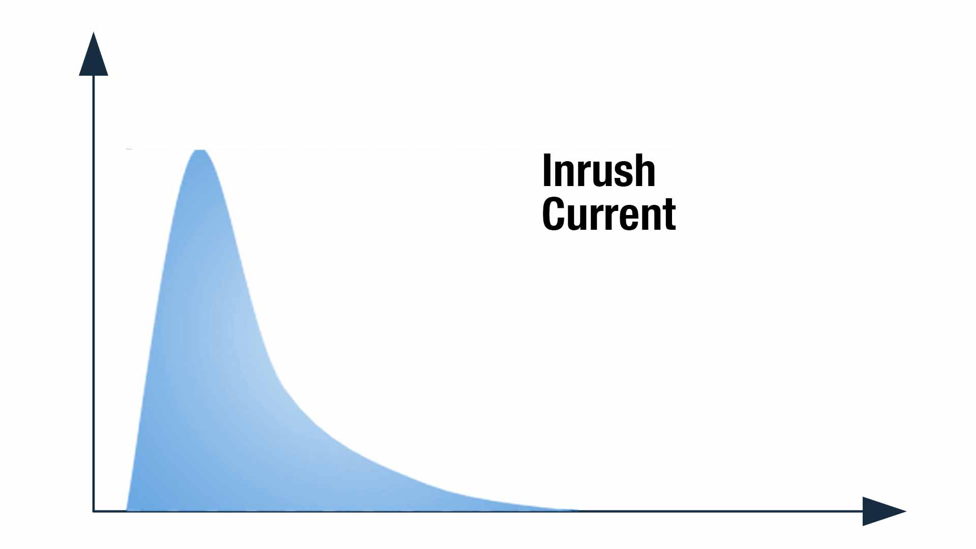
Before we get to the meat and potatoes, we have two more concepts to understand. The first is inrush current (also called surge current).
Inrush Current
Almost every device (including lighting fixtures and AC-to-DC converters that you find on chargers) requires an initial surge of current that is well over its rated capacity.
E.g., tungsten fixtures sometimes generate 10-20 times the rated current on start up. The same applies to HMI and fluorescent lamps, but to a lower degree.
Why is this important?
Let’s say you want to power a 100 Watt tungsten bulb on a 15 A circuit. Let’s assume the voltage is 120 V.
From our formula, the Amperes drawn is 100 / 120 = 0.83 A (the power factor for incandescent lights is 1).
If the inrush current is 15 times the rated current, the bulb will need an initial surge of 0.83 x 15 = 12.45 A. This value is lower than the specification of the circuit (15 A).
Then what if we use a 200 Watt bulb? Will that be a problem? No! Why not?
It doesn’t trip because breakers normally require that current flow for a specific minimum amount of time before it is deemed dangerous. An inrush current subsides in less than a second. As an analogy, it’s like a guinea pig stole your pants right under your nose – while you were wearing them – and put them back on again.
And, you didn’t notice a thing!
The duration of the inrush current is so minuscule that it hardly matters to the circuit. On the flip side, if the inrush current is too large, it will destroy your circuit.
How does inrush current affect lights used in filmmaking?
There are some neat tricks which the manufacturers don’t tell you about, but must be thanked for.
One such trick is to preheat a tungsten filament to lower its resistance. It still looks switched off, but it’s being heated. When you switch on the lamp, the inrush current is well below dangerous levels because of this.
You feel the light glows instantaneously and switches off instantaneously. Modern fluorescent and HMI electronic ballasts also have circuitry that greatly reduces the inrush current.
For small devices, the inrush current is negligible. For larger wattage lamps, it is higher, but not high enough to cause the mains supply any problems. Very few manufacturers specify the inrush current on their lamps, and as far as I know they are not required to.
If you can’t find the information, and the manufacturer doesn’t share it with you, assume the inrush current is 2 to 5 times the normal current.
The Voltage Wars
Most of the world offers either of these two standards (there are some exceptions):
| Voltage | 120 V ±5% | 230 V ± 10% |
| Frequency | 60 Hz | 50 Hz |
You have two choices:
- Live with it, or
- Buy a transformer and change the voltage for your house or facility.
There is one good reason for choosing the latter option.
If a device is rated for a specific power and power factor, and the voltage is constant, the only variable that can change is current.
Now, look at the two voltages available for mains: 120 V and 220 V. For the same wattage, a circuit rated at 120 V will draw more current than a circuit rated at 240 V. This means, to get the same power, you’ll need thicker cables and higher rated breakers.
Sometimes, on set, you’ll find electricians rigging portable generators with a transformer to raise the voltage. Some generators come with both 120 V and 240 V options for the very same purpose.
Even in homes, devices that need more current (like heaters, etc.) might work on 240 V even if everything else is at 120 V. Check the specifications of your light fixture or device to know what voltage is supported.
There’s another reason why you might want to change the voltage, and this when you’re traveling to a country whose electrical specifications are different from your own. And, you are carrying devices that won’t work.
Finally, you’re using transformers whether you know it or not. Ballasts for lighting fixtures have transformers too.
I need you to be aware of this, because you’ll see experienced gaffers using transformers on set. You, being a cheap low budget filmmaker, will probably not use one. So, let’s move on.
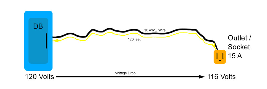
The Voltage Drop
The farther away the distribution board from a wall socket, the greater the fall in voltage. If you know the resistance of the cable being used you can calculate the voltage drop.
I promised no formulas, so you can skip this if you want.
The formula to calculate voltage drop is:
Voltage Drop = [Length (in feet) x Resistance (in Ohms/1000 feet) x Rated Amperes (A) ] / 500
If the distance between the DB and the wall unit is 20 feet, and you’re using a 10 AWG cable (Resistance = 1 Ohm/1000 feet), and the rated Amps is 15 A, the Voltage Drop = 0.6 V.
That’s peanuts!.
But for fun, if you want to take the same cable to the top of the Empire State Building (1,250 feet), the voltage drop is 37.5 V. This means the percentage drop is 31.25%.
That is not okay.
All you have to remember is this rule of thumb:
In most countries, the voltage drop is never allowed to exceed 5% (USA) or 4% (UK). You can assume the maximum is 5%, but there are many places in the world (especially in rural areas) where voltage drops are common.
All you have to remember is: The maximum length that would satisfy a 5% drop in Voltage is 200 feet.
Every circuit created in the distribution board is rated for a current, in Amperes.
This means:
- Cables will typically only work till that limit.
- A circuit breaker that will trip beyond that limit, and
- A wall socket that can only handle that limit.
If a circuit says 15 A, then the socket will be a 15 A socket, the breaker will be a 15 A breaker, and the cable will be of sufficient thickness just enough to handle 15 A.
If you want to change the ampere rating to something higher, you’ll need to change everything.
What is the Maximum Power you can get from a Household Mains Supply?
What options do you have for household circuits? In most cases, you have two options:
- The “normal” option – most of your appliances, lights, chargers, etc., will run on this.
- The “higher-up” option – more demanding appliances like ovens, refrigerators, air conditioners, etc., will run on this.
This system has been followed since the dawn of electricity distribution. Depending on the country you live in, the normal and higher-up option(s) will vary.
Here are two examples for the US and the UK:
| UK | Frequency (Hz) | 50 | |||
| Voltage (Volts) | 230 V ± 10% | ||||
| Max Current (Amperes) | 5 | 13 | 15 | 30 | |
| Max Apparent Power (W) | 1200 | 3120 | 3600 | 7200 | |
| USA | Frequency (Hz) | 60 | |||
| Voltage (Volts) | 120 V ± 5% | ||||
| Max Current (Amperes) | 15 | 20 | 30 | 50 | |
| Max Apparent Power (W) | 1800 | 2400 | 3600 | 6000 | |
It is obvious, that at the same Ampere rating, you get less power (about half) on a 120 V system than a 240 V system.
Probably the most common ampere rating circuit is 15 A (sometimes also 13 A or 16 A).
A 15 A socket can only deliver a maximum of 3.6 KW in the UK, and 1.8 KW in the US. However, this theoretical maximum is not available to you.
The 80% rule
Some laws and regulations state that a circuit must not be loaded to greater than 80% of its capacity.
Due to this, on a 15 A circuit, you get:
- 2.9 KW in the UK, and
- 1.5 KW in the US
A 20 A or 30 A will give you more power. The regulation is there for a good reason: Many of the wiring we have around are older than our parents. It is not wise to run 15 A through a 15 A rated wire from another era. What if someone used cheap and poor quality wires or breakers while wiring the house?
As a rule of thumb, if you’re in an old location, follow the 80% rule.
What to do when you Walk into a Location
Let’s say you’re in a location with two 5 A circuits, two 15 A circuits and a 20 A circuit to play with (this is imaginary, so play along).
Does this mean we get a total of 2×5 A + 2×15 A + 20 A = 60 A? Nope. Let’s not get ahead of ourselves.
Let’s take this step by step.
Step 1: Study the Wall Sockets
Count the number of sockets. In this example, we have five of them.
Some sockets have the ampere rating written on it. If nothing is written on it, you might want to call an electrician to know exactly what the rating is. You’ll also want to know two other things:
- Whether or not the socket has a fuse. If yes, what is its rating? Does it match the socket’s rating? Hint: It should!
- What is the thickness of the cable used? I’ll talk about this a bit later.
You write down this information clearly, and then ask for the distribution board or panel. If it’s a commercial space, it most likely will be on the same floor. For older offices and homes, it might be on the ground floor.
One other thing you want to inspect is the socket type. Is it a 2-pin or 3-pin socket? What kind, exactly? You need to ensure your gear has plugs that will match the sockets.
Step 2: Measure the Distance of the “Walk”
From the socket to the distribution board, how long is it (in feet)?
Don’t forget that cables snake through walls, the ceiling or the floor, and not straight as an arrow.
If the distance is just a few hundred feet, the voltage drop is negligible.
Also, which distribution board are you at? Here are some options:
- Electrical room of a building or complex.
- Main Distribution Board (MDB) of a building.
- Distribution Board of an apartment, house or office or floor.
- Panel or distribution board of an apartment or home.
The goal is to find a DB that’s closest to the socket you want to use.
If you start at an electrical room of a large complex but are only interested in two sockets in one room of a single apartment, you should look for the MDB of the building.
Or, even better, the DB on the floor or the apartment.
How do you know when you are close enough? Ask yourself: Where do you have maximum control to read and manipulate power if it came to that? That’s your ideal beginning location.
E.g., if you have access to the electrical room, but are not allowed to draw power from it directly, what the hell are you doing there anyway?
Step 3: Study the Distribution Board
Open the distribution board. Exciting, isn’t it? I hope you’re wearing insulated gloves.
If it’s a branded DB it’ll have a drawing on the back of the cover (or some other place) with information on how it is wired.
Unfortunately, many boards will look like this (on a good day!):

Your job is to find which sockets go to which circuit breaker (MCB) on the distribution board. If the information isn’t written on the board, and no one knows, the simplest way to test it is to get someone to plug in something at the socket and switch off the breaker to see if it stops.
If you want a tool that will do the job for you, look for a Circuit Breaker Finder. I know you are not going to buy that.
Every location presents its own challenges. Don’t assume, just because a building is ultra-modern on the outside and sits in the heart of the business district it will have good wiring.
Also, never assume a run-down home or location has bad wiring. In short, don’t make assumptions.
At the distribution board, check to see if the cables that you saw in the socket end up here as well. If not, then you know there’s a “joint” somewhere in between. If there is, you might want to investigate where it is to see if it’s just a simple joint or whether there’s something else going on that shouldn’t be happening.
Once you’ve found the circuits, it’s time to look at the cables.
Step 4: The Secret of the Cables
Cables are important! No matter what the ratings say, if a cable can’t support a certain ampere level, current will not flow.
Here are the approximate (Please don’t use this information! Please refer to your local standards and laws. This is just a rough indication for information purposes) values of cable sizes against Ampere draw:
| Cable required | |||
| UK | USA | ||
| Required Amps (A) | Square mm | AWG | Square mm |
| 6 | 0.75 | 14 | 2.08 |
| 8 | 1 | 13 | 2.62 |
| 12 | 1.5 | 11 | 4.17 |
| 17 | 2.5 | 9 | 6.63 |
| 22 | 4 | 8 | 8.37 |
| 29 | 6 | 7 | 10.5 |
| 40 | 10 | 5 | 16.8 |
| 54 | 16 | 4 | 21.2 |
| 71 | 25 | 3 | 26.7 |
| 87 | 35 | 2 | 33.6 |
| 105 | 50 | 1 | 42.4 |
| 135 | 70 | 1 (1/0) | 53.5 |
| 165 | 95 | 00 (2/0) | 67.4 |
| 190 | 120 | 00 (2/0) | 67.4 |
| 220 | 150 | 000 (3/0) | 85 |
A professional electrician would study the cable size and refer to the manufacturer’s data sheets. There is no easy way. The good news is, once you’ve successfully estimated your requirements on many projects, you’ll start to get a hang of things.
There is one kind of circuit where the cable size can throw you off, and that is a Ring Circuit, which is mostly found in the UK. In this case, the cable is usually only about 60-70% of the total, because two wires share the load equally.
Step 5: Understand the Circuits
It’s only in rare cases (air conditioner, heater, etc.) that a complete circuit is dedicated to one socket. For general appliances and lights, you have multiple points per circuit.
E.g., a 15 A circuit can be divided between two sockets (outlets) or more. If they’re both being used, they will have a total capacity of 15 A, and must share that. Some older homes might have 5-10 sockets per circuit! This is obviously bad because it reduces the power of each outlet (assuming all of them are being used at the same time).
You’d want to isolate the outlets according to their circuits. This gives you the freedom to choose what fixture goes where.
In our example, we have two 5 A outlets and two 15 A sockets share the same circuit. The 20 A socket is on its own breaker.
See? This is why we don’t get 60 A.
Step 6: Take a closer look at the Circuit breakers
Single-phase circuit breakers are rated at standard values. The most common being: 6 A, 10 A, 13 A, 16 A, 20 A, 25 A, 32 A, 40 A, 50 A, 63 A, 80 A, 100 A and 125 A.
Look on the breaker itself, and you will see it in big bold lettering. Any breaker that falls within these limits is a Miniature Circuit Breaker (MCB). Household and Office circuits needn’t go over 100 A (total) normally.
Now look at the main breaker (that attaches to the mains supply cable). It will be rated higher. Let’s not worry about its name, but only two things:
- Is it single-phase or three-phase?
- What is its Ampere rating?
Knowing the total power coming into the house or office will tell you whether the circuits made from it are okay (or disasters waiting to happen).
Whatever you do, don’t assume the main breaker’s ampere reading must be the sum of all the individual breakers’ readings. That’s not how it works.
If you add up the amps on each MCB, you’ll notice it is always greater than the amps on the main breaker. Does this mean the circuit is overloaded? Of course not.
Just like Internet and Wi-Fi bandwidth is always oversold (because not everyone uses all of it at the same time), electricity is also a scarce and expensive commodity.
Every socket is not always connected to a device, and every light in a building is not always turned on at the same time. Some devices, like heaters or air conditioners, are turned on at the same time depending on what season it is.
Look at how many rooms, apartments, houses or offices a distribution board is feeding.
Here’s a rule of thumb: The more the houses the more the difference between the sum of the breakers and the main breaker. E.g., if you live in a hut in a small village, even 100 Watts is precious and you can bet you’ll use every last drop of it.
On the other hand, if you’re staying in a modern high-rise, with more than 100 apartments, then the difference can be almost 50%. In any case, the ratio of the sum of amps of each MCB and the main breaker must be between 40% to 100%, and never less than 40%, as a rule of thumb.
Note down the ampere rating on the breaker – for each circuit you care about.
In our example case, let’s say we’ve identified three breakers (three circuits), and the ampere ratings are 5 A, 15 A and 20 A.
Now we can put it all together.
Step 7: Whatever’s Left Must be the Truth
If the breaker, sockets and cables seem okay, you know the circuit is capable of carrying the ‘advertised’ ampere rating. If any of the links in the chain is not capable of carrying the rated current, the circuit must be ‘down-rated’ to what it can carry.
In our test case, we know our outlets will give us 5 A and 15 A (but not at the same time, because they are shared), and 20 A.
Our takeaways from this investigation are these values:
- The ampere ratings of each circuit
- The voltage ratings of each circuit
- The 80% rule
If you’re crying for an easier and more accurate way to do this entire thing, then here it is. Just measure everything at the outlets with a Power Meter:

You’ll have all your answers in ten minutes.
Anyway, I know you’re not going to buy one, so let’s do the math instead. The good news is, it’ll also take only ten minutes!
How to use the power formula
The formula for power applies to every possible thing in a circuit – separately. It applies separately to the circuit breaker, the line wire, the socket, the ballast and the lamp, etc.
I’m going to simply things, and divide it into two parts:
- What the outlet is capable of giving.
- What the light fixture wants.
This means, you will be using the formula twice – one for the socket and one for the lights.
The goal is to get the power ratings for the fixture lower than the socket. If it’s higher, you can’t use that fixture on that socket.
Calculating at the socket
Our only formula again:
W = V x A x PF
We know about voltage drops (-5%) and the 80% rule. So let’s slightly modify our formula (ignore the power factor because the outlet isn’t drawing any current from your lights):
W = (V x 95%) x (A x 80%)
The values for 120 V and 230 V are as follows:
| Country | Voltage (V) | Amperes (A) | Max. Power (Watts) | |
| All outlets together | If shared equally | |||
| US | 120 | 5 | 456 | 228 |
| 120 | 15 | 1,368 | 684 | |
| 120 | 20 | 1,824 | n/a | |
| UK | 230 | 5 | 874 | 437 |
| 230 | 15 | 2,622 | 1,311 | |
| 230 | 20 | 3,496 | n/a | |
Wow. We now know how many Watts of real power each outlet is capable of delivering in our example case.
But that’s just one step.

Calculating at the fixture
Let’s make this challenging.
Let’s say we need a couple of Arri 4K HMI PARs, a couple of 1.2K HMI PARs, four 650 W tungsten fresnels, and a few LED 1x1s. We also need one outlet to charge two 90 Wh batteries and run a Macbook Pro at the same time!
Can all this run on the five outlets we have?
The formula first (get used to it):
W = V x A x PF
What we want are two values of A – the operating current and the inrush current. We start with our biggest fixtures, the 4K HMI PARs. If you’re using an electronic ballast, the power factor (PF) = 0.98.
The maximum power of the 4K fixture is 4,650 VA, or 4,557 Watts. Looking at our table above, we can see there isn’t a single socket that can deliver this power. For this reason, you can forget about the 4K lights!
Side note: You can connect a 4K HMI in a 30 A socket if the voltage is 230 V, but not in 120 V. It’s rare though.
The maximum power of the 1.2K fixture is 1,390 VA, or 1,362 Watts. It will just about ‘fit’ in a 15 A circuit (US). It will also fit in a 20 A circuit (US), and the 15 A and 20 A circuits in the UK.
Important note: The inrush current for HMI fixtures isn’t very high, for reputable manufacturers. If the power factor is low, or if there’s a high inrush current, these numbers will change.
In this scenario, you might decide to use four 1.2 K HMIs to make up for not having 4K fixtures, or use 1.2K bulbs in an M18, and so on.
Wait. Can you plug in four 1.2K HMI fixtures? Not in the US.
At best, you can power two 1.2K HMI fixtures, one in the 15 A socket and the other in the 20 A outlet.
In the UK, you can power three of them (two in the 20 A circuit and one in the 15 A circuit). You might be able to squeeze in another 1.2K fixture in the 15 A circuit because it’s very close, and the power rating we’re taking into account is the maximum power rating, not the lamp rating which is lower. However, what might spoil your party is the inrush current, which might not allow you to strike the fourth lamp.
With a sigh, you decide to use just two 1.2K HMI fixtures. You need them.
This leaves you with these options:
- In the US – one 5 A circuit to play with.
- In the UK – one 5 A circuit and one 15 A circuit to play with.
What about the four 650 W tungsten fresnels? Since the power factor is 1, each 650 W fixture will eat up 650 Watts of power.
If you’re in the US, it’s a no-go, because your remaining 5 A circuit can only accommodate 456 Watts. Even if you tried to squeeze one of them in the 20 A circuit, you can’t (1,824 – 1,362 = only 462 W)!
In the UK, you can accommodate all four 650 Watt fresnels into a 15 A circuit, provided you switch them on one at a time (to give each one its inrush current cushion). Typically, you must switch them on one at a time, in the order from largest to smallest, current draw-wise.
With the one 5 A circuit left, assuming you have a PF of 1, you can plug in:
- A 90 Wh charger – about 200 Watts, and a
- 15″ Macbook Pro – about 100 Watts.
What about the LED 1 x 1s?
Let’s say each 1×1 light is rated for 40 Watts. Their power factor PF is about 0.54. This means, the real power draw is 74 Watts. Four 1x1s would need 296 Watts. In both countries, you can connect the 1x1s in one of the outlets that have not maxed out.
Here’s how things pan out for our fantasy production:
| US | UK | |
| Wishlist | 2x 4K HMI, 2x 1.2K HMI, 4x 650 W Tungsten, 4x 1×1 LEDs, 90 Wh Charger and Laptop | |
| Reality | 2x 1.2K HMI, 4x 1×1 LEDs, Charger and Laptop | 3x 1.2K HMI, 4x 650 W Tungsten, 4x 1×1 LEDs, Charger and Laptop |
Life isn’t fair on one side of the Atlantic, that’s for sure!
Team UK gets 3x 1.2K HMIs and 4x 650 W tungsten fresnels. Team US gets only 2x 1.2K HMIs and no fresnels.
This is how you estimate if your lighting fixtures and equipment will work on a single-phase mains supply. Remember, I’ve been conservative with my ‘guesstimating’, and you should be, too.
A good electrician might help you squeeze in an extra light or two, but that’s something you shouldn’t assume at the beginning.
Now let’s look at portable generators.
How are Portable Generators different from a Mains Power Supply?
There are two major differences between portable generators (or any generators for that matter) and the mains supply:
- You have to keep tabs on what you put in, which is fuel and oil.
- You have to keep tabs on the kind of devices you plug in, or you won’t get all the power the generator is capable of.
Because of these differences, you must know your generator well in order to get the best out of it. It’s not as forgiving as a mains supply.
For the purposes of this article, I’m going to assume you either have a working knowledge of running a portable generator or have the assistance of an electrician.
Total Harmonic Distortion (THD)
This isn’t about music.
Imagine relaxing on a beach with your favorite drink, taking in the fresh air.
Breathing in an open space is like drawing power off the mains.
On the other hand, imagine sitting in a closed room with many other people. It only takes one person to ‘spoil’ the air for everyone (use your imagination). This is what it’s like to draw power from a generator.
Almost every kind of device used on a film set is detrimental to each other in this manner. This includes chargers, computers, monitors, ballasts, lights, and so on. They all “spoil the air” to a certain extent. Some more than others.
Devices introduce currents into the system that spoil the quality of the generator’s current. This affects every other device plugged in. As you can imagine, the worse for the generator, the worse for everybody in return.
This ‘spoiler current’ is called a harmonic. And, the distortion (reduction in quality) of the overall current the generator supplies due to harmonics is called harmonic distortion.
The Total Harmonic Distortion or THD is the measure of the total distortion caused to the generator by all the devices connected to it. Once this crosses a certain threshold, it will cause the generator to overheat, and possibly stop.
Large generators (like ones used for large productions) have circuitry to deal with THD. You’ll probably be using a portable generator.
By portable, I mean a generator that can be carried or pulled by one individual. Such generators typically do not have circuitry to deal with large amounts of THD. Cross the threshold, and you’re done.
The sad part is, there’s nothing much you can do as a filmmaker except choose the right lights and generators. Since lights are not always ‘negotiable’, choosing the right generator becomes critical.
Which Portable Generators are the Best?
We cannot go into detail here without getting into electrical engineering specifics. But, to summarize, here are some important considerations:
- An inverter generator produces the cleanest electricity with the most stable voltage. You need this if you’re running sensitive equipment like laptops, cameras, etc.
- Petrol/Gas or diesel generators are efficient. However, in some countries, fuel is scarce, and might be illegal to buy separately. Kerosene generators are a viable replacement.
- A good generator should have more than one outlet, and preferably the option to choose between 120 V and 230 V.
- Silent generators are often critical for films that require production audio.
- The larger the fuel tank, the more fuel a generator can carry, and the more it can run on a full tank. This will save you trips to the gas station.
- You must have the means to transport the portable generator to the location and back. In other words, it must fit your van or truck.
- An electric start is easier to handle than pulling a rope cord.
- The higher the power rating the better, but only if you need it!
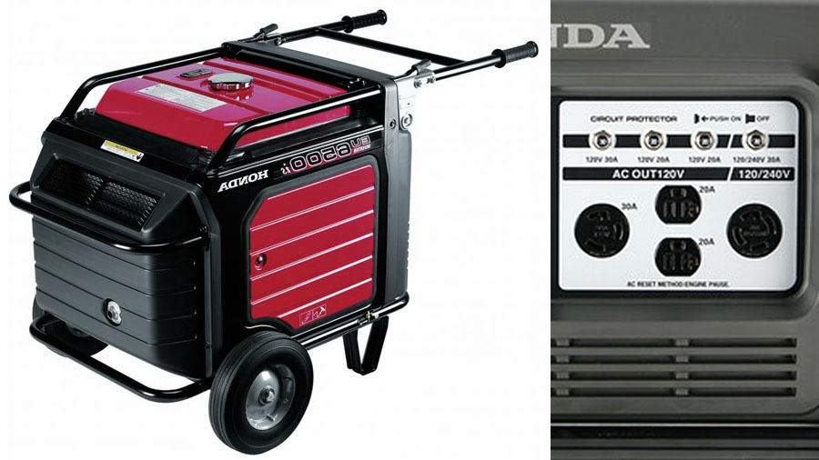
Probably the most well-know brand of generator in our industry is Honda, and the two generators I’ll use as examples for the rest of this article are:
How to read Numbers on a Honda Portable Generator
There are two numbers: the model number, and the specifications of the generator.
The Model Number
The model “number” is easy:
E stands for generator. Every Honda generator starts with an E.
U stands for ‘ultra-quiet’. This means it’s a silent generator.
The numerals stand for the maximum power rating (not the standard load, see next section).
I stands for ‘Inverter’, the cleanest power supply possible.
S stands for electric start. As you can see, model 2000 does not have an electric start (the 3000 does though).
The Specifications
A generator name plate should display this information. What we need is listed in the following table:
| Honda EU2000I | Honda EU6500IS | |||
| @Voltage | 120 V | 240 V | 120 V | 240 V |
| Maximum Power | 2000 Watts | 6500 Watts | ||
| Rated Power | 1600 Watts | 5500 Watts | ||
| Maximum Current | 16.7 A | n/a | 54.1 A | 27.1 A |
| Rated Current | 13.3 A | n/a | 45.8 A | 22.9 A |
| 20 A Outlet Duplex^ | 2 | n/a | 2 | n/a |
| 30 A Outlets | n/a | n/a | 1 | 1 |
| DC Output | 12 V, 96 Watts, 8 A | n/a | ||
| Fuel Tank Capacity | 0.95 Gallons (3.8 L) | 4.5 Gallons (18 L) | ||
| Run time at Rated Load | 4 hours | 4.7 hours | ||
| Run time at 1/4 Load | 9.6 hours | 14 hours | ||
| Noise at Rated Load | 59 dBA | 60 dBA | ||
| Dry Weight | 46.3 lbs (21 kg) | 260 lbs (119 kg) | ||
| Weight of Fuel | 5.85 lbs (2.7 kg) | 28 lbs (12.5 kg) | ||
| What you need to lug around | 55 lbs (25 kg) | 300 lbs (150 kg) | ||
How far should the Generator be for Production Audio?
Both generators have a noise level of about 60 dBA, measured at 9 feet (3m) from the control panel side. This is equivalent to a normal conversation or the noise of the television running at normal volume.
Obviously, it is too loud for production audio.
The threshold for production audio is about 20-25 dB. Let’s use 20 dBA as our limit.
How far should you go to get 60 dBA to reduce to 20 dBA? Without boring you with the math, you must take the generator about 180-200 feet away from the set, at least.
Now this introduces a problem – that of voltage drop. If you use the right cable, the drop should not be greater than 5%. We need to factor this into our calculations.
How to Estimate if your Film Lights will Work on a Portable Generator
The simplest and most accurate way to test how much power your devices will draw is by testing it with an appliance load tester. I know that’s not for you, right?
The rated Watts on a generator is the real power it is able to deliver over long periods of time. You shouldn’t use the maximum or peak power, which is an overhead for surge currents and is only available for about 30 minutes (for Honda generators).
Let’s return to our fantasy production. Can we power 4K HMIs, 1.2K HMIs and 650 W tungsten fresnels on our generators?
Here are the results:
| Power available from the Generator | ||||
| Honda EU2000I | Honda EU6500IS | |||
| @Voltage | 120 V | 240 V | 120 V | 240 V |
| Maximum Power | 2000 Watts | 6500 Watts | ||
| Rated Power | 1600 Watts | 5500 Watts | ||
| Maximum Current | 16.7 A | n/a | 54.1 A | 27.1 A |
| Rated Current | 13.3 A | n/a | 45.8 A | 22.9 A |
| Outlets | 20 A x 2 | n/a | 20 A x 2, 30 A | 30 A |
| DC Output | 12 V, 96 Watts, 8 A | n/a | ||
| Power required by lighting fixtures and devices | ||||
| @Voltage | 120 V | 240 V | ||
| @Voltage (-5% drop) | 114 | 228 | ||
| 4K HMI Rated | 6200 VA | 4650 VA | 6200 VA | 4650 VA |
| Power Factor | 0.7 | 0.98 | 0.7 | 0.98 |
| Current Draw | 55 A | 41 A | 27.2 A | 20 A |
| 1.2K HMI Rated | 2290 VA | 1390 VA | 2290 VA | 1390 VA |
| Power Factor | 0.6 | 0.98 | 0.6 | 0.98 |
| Current Draw | 20 A | 12 A | 10 A | 6 A |
| 650 W Tungsten | 5.7 A | 2.9 A | ||
| Dual Dionic Charger | 1.75 A | 0.9 A | ||
| Macbook Pro Retina | 0.9 A | 0.5 A | ||
On the Honda EU2000I
The maximum nominal current it can supply is 13.3 A. As you can see, all you can hope to run on it is one 1.2K HMI and either the charger or the Macbook Pro.
Even then, it’s pretty close.
Things that ruin our calculations are: Older generators, poor maintenance, rough use, cheap quality spare parts, etc. When the numbers are close, you can’t know for sure unless you test the actual fixtures you’re going to use.
On the Honda EU6500IS
This generator is more promising.
You can run one 4K HMI (with a power factor corrected electronic ballast) on it, for sure. After you strike the 4K HMI first, you will have enough left over to light a 650 W tungsten fresnel, but it will be a close call.
Otherwise, you can easily run the 90Wh charger and a Macbook Pro.
On the other hand, if you don’t want a 4K HMI, you can fire up two 1.2K HMIs, one tungsten fixture, the charger and the laptop. Just as a side note, you can also fire two 2.5K HMIs on the EU6500IS portable generator, instead of the 4K and 1.2K HMI.
It is wise to switch on each device one at a time, starting with the largest in terms of Ampere draw.
And, one more:
Important: You shouldn’t run a portable generator in a closed room or environment. The fumes are dangerous!
That’s how it’s done.
Just use one formula, common sense and the right values. Using this system, you can estimate your requirements for any fixture, device or gear.
Don’t forget there are other kinds of generators (not the inverter kind) that demand considerations like voltage regulation, etc. You can’t stretch the little knowledge provided in this article to all scenarios. That would be a dangerous mistake!
I recommend testing your lights with the generator you’re renting or buying, with a certified electrician (preferably a film lighting technician, Best Boy or Gaffer). Once you know how it’s done, you should be able to safely handle things on set.
It’s worth it!
I have the choice of both Mains and Portable Generator. Which One do I Pick?
Cost is probably the most important consideration here.
The cost to rent an EU6500IS can be about $150-250 per day (it’s cheaper on a per-week basis). If you can get by with 6 gallons of fuel at $3.50 per gallon, you’ll pay about $20 per day for fuel. That’s shy of $200 per day for the privilege to use a few HMI lights.
If the location charges you 20 cents per KiloWatt-Hour (KWH), you’ll be paying about $9-10 per day.
It’s hard to justify a generator price-wise, on a low budget film.
How else could you justify it? E.g., you can run a 4K HMI on a generator in the US, but not off the mains supply (not without some electrical expertise, anyhow).
All said and done, you’re more likely to use a generator in an open environment where there’s no mains available.
As a rule of thumb, it’s always cheaper (and faster) to use the mains supply if it suits your needs.
Three-phase Mains
I left three-phase mains supplies for last because it’s rare you’ll find a three-phase outlet to connect to. Most devices run on single-phase power.
These are rare and extreme cases beyond the scope of the average indie production.
Here’s what a typical 3-ph plug looks like:

PE is earth. N is neutral. In 3-ph power, neutral is not always required, so you might have only four pins.
The receptacles look something like this:

Here’s how single-phase and three-phase voltages are related:
| Voltage (V) | Single-phase | Three-phase |
| USA | 120 | 208 |
| UK | 240 | 415 |
You can create a single-phase circuit by just using one line/phase and one neutral (if it exists). A lot of the times, the outlet/socket won’t allow you to directly plug in a single-phase device, so you’ll need an electrician to create a 3-phase to 1-phase distribution board with the proper breakers and connections. This is the safest way that meets regulations.
You need to be careful about the wiring. E.g., if you connect a 240 V device to a Line-Line circuit (208 V in the USA), you’ll only be getting 208 V.
There are some “gotcha’s” while running single-phase off three-phase sockets.
A big one is load balancing. If there’s a neutral wire, and each 1-ph circuit draws a different amount of current, the current flowing through the neutral will be more than an any line.
Secondly, unbalanced loads cause harmonics (you know this is bad), and this reduces the efficiency of the circuit. You might find adapters that convert three-phase sockets to one single-phase socket, but anything more complicated demands the attention and resourcefulness of an electrician.
You might be wondering: How many single-phase circuits can you make from a three-phase circuit? It doesn’t work that way!
How many devices can you connect to a single-phase socket? It depends on current, not voltage. It’s the same with three-phase to single-phase conversions. It’s not the voltage that decides how many circuits you can create, but the total amperes available. The rating will be written on the socket.
Luckily, most locations that come with three-phase sockets will also have in-house electricians – factories, auditoriums, garages, etc. Use their expertise. Even if you hire a Gaffer or Best Boy Electric, he or she could use their know-how to get things done faster.
There you have it. All the best for your production. Stay safe, and take the help of a Gaffer, Best Boy or Lighting Technician. It’s worth it.